
 FAQs
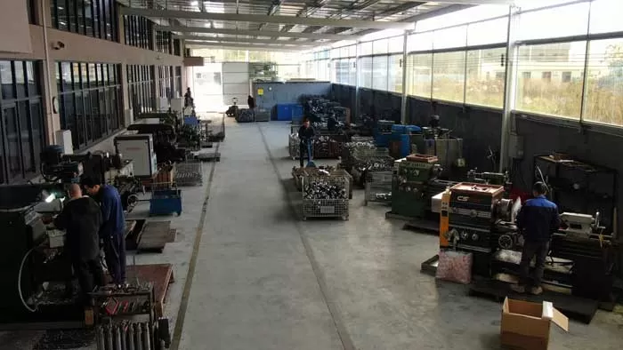
FAQs Factory Tour



Flat glass processing requires rigorous control over surface tension, edge stress distribution, and mechanical tolerances. Raw glass sheets produced via the float process possess micro-fissures along their cut lines. These structural imperfections significantly reduce the mechanical bending strength of the substrate and create high localized stress points. Left untreated, unground glass edges lead to elevated failure rates during subsequent thermal tempering, handling, and installation. Integrating an industrial glass edge machine into the fabrication line directly addresses these material weaknesses by systematically removing edge defects, forming standardized profiles, and preparing the sheet for structural applications.
Automated edge grinding and polishing represent a primary manufacturing step in architectural, automotive, and appliance glass production. Transitioning from basic manual seamers to multi-spindle CNC machining systems allows industrial fabricators to meet strict geometric tolerances while maintaining repeatable yield rates. Equipment engineered by manufacturers such as BAINENG CNC incorporates rigid frame design, closed-loop servo control, and precise coolant delivery to achieve consistent surface roughness values (Ra) across high-volume production cycles.
Micro-Fracture Physics and Edge Profile Kinematics
The primary mechanical function of edge processing is the mitigation of sub-surface damage (SSD). When raw glass is scored and snapped, the break line exhibits micro-cracks extending into the bulk material. Applied thermal or mechanical loads concentrate at these micro-fissures, leading to catastrophic failure at strain levels far below the theoretical tensile strength of silicates.
Material removal using diamond abrasive wheels operates in a regime balancing brittle fracture and ductile machining. By utilizing progressively finer diamond grit sizes, processing equipment removes the cracked outer boundary of the glass sheet, reducing stress intensity factors. The choice of profile depends directly on the final application of the glass panel:
Flat Edge with Arris: The standard profile for architectural paneling, structural glazing, and insulated glass units (IGUs). The process grinds the primary perimeter flat while applying top and bottom 45-degree chamfers to eliminate sharp corners that induce thermal stress.
Pencil Edge (C-Shape): Featuring a rounded radius, this profile is widely used in automotive windows, mirror fabrication, and decorative furniture. The smooth contour minimizes edge chipping during mechanical movement.
Beveled Edge: Created by applying a angled grind (ranging from 3 to 45 degrees) along the glass margin, followed by multi-stage polishing. Used heavily in mirror manufacturing and high-end decorative glazing.
OG and Custom Profiles: Complex multi-radius curves achieved via multi-axis CNC routing, targeted at specialized interior architecture and luxury fixture manufacturing.
Core Machinery Components and Mechanical Tolerances
Achieving sub-micron surface finishes on brittle substrates demands exceptional dynamic rigidity from the processing equipment. Any vibration transmitted through the machine bed introduces chatter marks on the glass edge, leading to stress concentration points and shortened tool life.
Spindle Assembly and Dynamic Stability
The spindle unit forms the core drive mechanism of the machining station. High-precision electric spindles equipped with ceramic hybrid bearings are utilized to minimize thermal expansion during continuous operation. Spindle runout must be maintained within limits under 0.005 mm to prevent uneven wheel wear and edge shelling. Multi-spindle inline configurations allow sequential rough grinding, fine grinding, arrissing, and polishing in a single pass without manual re-indexing.
Chassis Construction and Drive Mechanisms
Heavy-duty structural steel, stress-relieved via post-weld heat treatment, serves as the structural foundation for high-performance processing hardware. A rigid chassis absorbs high-frequency vibrations generated during abrasive contact. Movement along linear axes utilizes precision ball screws or helical rack-and-pinion drives coupled with high-resolution absolute encoders. System architectures developed by BAINENG CNC utilize robust bridge frames and ground linear guides to preserve positioning accuracy across long processing spans, ensuring straightness tolerances within tight operational margins across full-sized jumbo sheets.
Abrasive Wheel Selection and Tooling Layout
The tool stack along a continuous machining line follows a strategic progression of abrasive media:
Metal-Bonded Diamond Wheels: Utilizing coarse diamond grit sizes (mesh range 80 to 140) set in a bronze or steel matrix for high-volume stock removal and initial profile formation.
Resin-Bonded Diamond Wheels: Employing finer diamond particles (mesh range 200 to 400) to smooth out deep mechanical scratches produced during initial grinding stages.
Polishing Wheels: Composed of synthetic rubber, polyurethane, or felt impregnated with cerium oxide particles. These wheels produce optical clarity, eliminating residual micro-scratches and yielding a smooth, continuous surface finish.
Coolant Fluid Dynamics and Thermal Management
Grinding brittle materials generates localized thermal energy at the contact zone between the diamond abrasive and the glass substrate. Rapid localized heating, followed by uneven cooling, causes micro-thermal shock, leading to sub-surface fracturing and compromised edge strength. Adequate coolant management is mandatory to maintain process stability.
High-volume water distribution systems direct focused streams of coolant directly at the contact interface. The fluid serves three operational functions: cooling the diamond tool matrix, removing abraded glass particulate matter (swarf) from the wheel face, and lubricating the interface to prevent glass micro-welding.
Maintaining clean coolant via multi-stage filtration—such as centralized settling tanks, magnetic separators, or automatic hydrocyclones—is necessary to prevent recirculated glass particulate from scratching polished surfaces. Operating a glass edge machine with contaminated fluid accelerates wheel loading, increases power consumption on the spindle motor, and degrades final surface finish quality.
Process Optimization and Operational Parameters
Achieving consistent processing output requires precise balancing of line speed, spindle speed (RPM), feed rate, and removal depth. The matrix below outlines standard operational settings across standard clear float glass thicknesses:
| Glass Thickness (mm) | Primary Grind Removal (mm) | Spindle Speed Range (RPM) | Line Speed Range (m/min) | Coolant Flow Rate (L/min) |
|---|---|---|---|---|
| 4.0 | 0.5 - 1.0 | 2800 - 3200 | 3.5 - 5.0 | 120 - 150 |
| 6.0 | 1.0 - 1.5 | 2800 - 3000 | 2.5 - 4.0 | 150 - 180 |
| 10.0 | 1.5 - 2.0 | 2400 - 2800 | 1.5 - 2.5 | 180 - 220 |
| 12.0+ | 2.0 - 3.0 | 2200 - 2600 | 0.8 - 1.8 | 220 - 250 |
Thicker glass plates require lower throughput speeds and higher coolant flow rates to manage increased material displacement volume. Exceeding recommended line speeds for a given thickness results in edge shelling, profile distortion, and premature wheel failure due to mechanical overload.
Integration within Automated Glass Processing Lines
In modern B2B manufacturing plants, standalone equipment is increasingly integrated into fully automated processing lines. Conveyor systems equipped with soft, wear-resistant rubber belts and non-marking support rollers transport glass sheets seamlessly between washing machines, edging stations, drilling centers, and furnace loading areas.
Automated thickness measuring devices at the inlet section transmit dimensional data directly to the central machine controller. Industrial CNC platforms adjust spindle positioning, pneumatic pressure settings, and guide rail widths dynamically without requiring operator intervention. Line architectures offered by BAINENG CNC feature standard industrial communication protocols, facilitating integration with factory MES (Manufacturing Execution System) environments for real-time tracking of operational metrics, maintenance schedules, and wheel wear patterns.
Frequently Asked Questions
What mechanical factors cause edge shelling during processing?
Edge shelling—where small, shell-shaped chips break off the glass corner—is primarily caused by excessive feed speed, improper wheel alignment, dynamic vibration in the spindle, or worn diamond tooling. Incorrect pneumatics or improper clamping pressure along the conveyor can also cause mechanical deflection of the sheet during grinding.
How does edge grinding quality impact thermal tempering results?
Thermal tempering introduces high compression layers on the outer surfaces of the glass while creating tensile stress within the interior core. If micro-fractures remain along the edge post-grinding, tensile stress during heat treatment concentrates at these crack tips, causing the glass sheet to shatter inside the furnace. Proper fine grinding and arrissing significantly improve tempering success rates.
What is the functional difference between straight-line double edgers and vertical CNC machines?
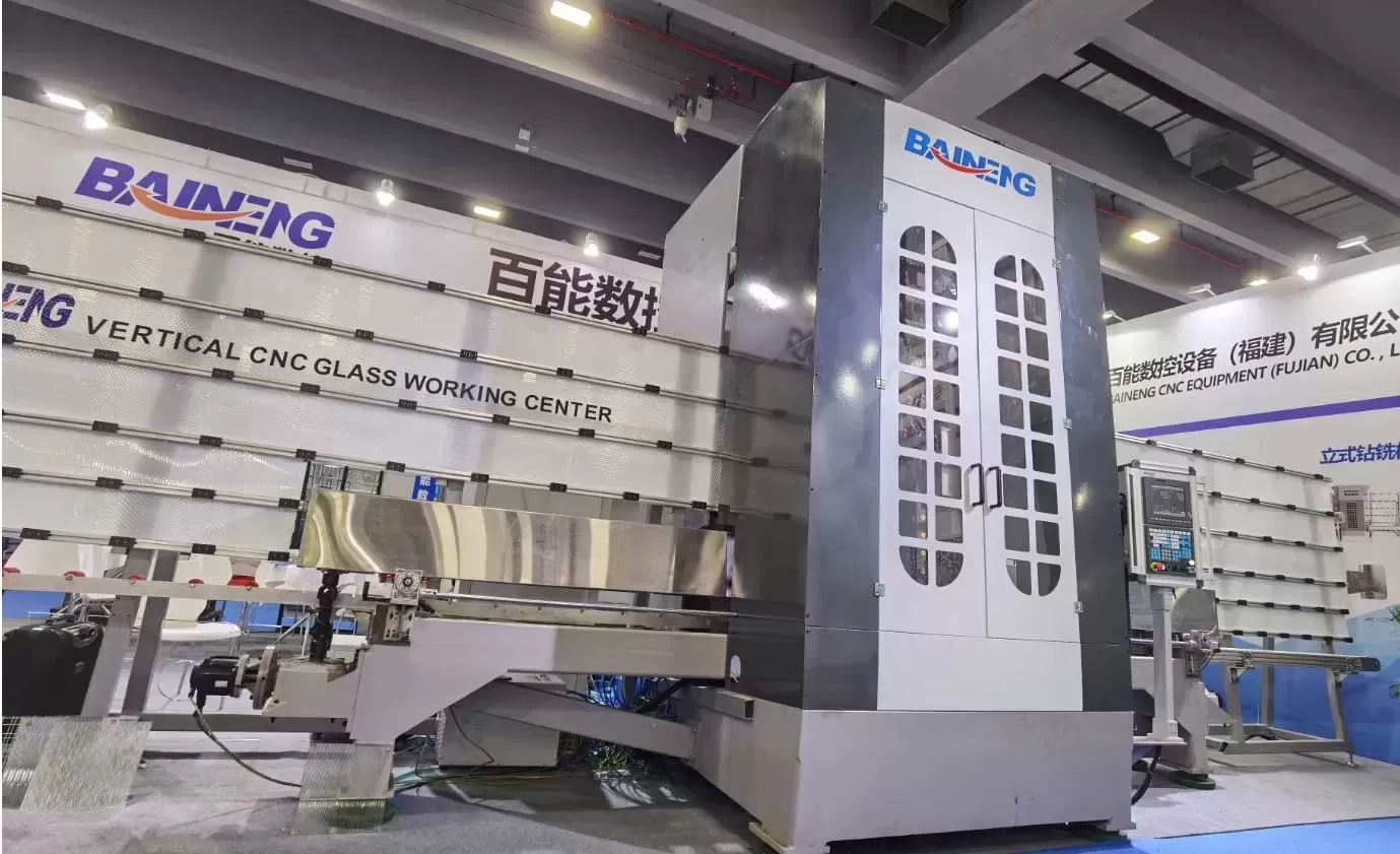
Straight-line double edgers process two parallel flat edges simultaneously on rectangular sheets at high speed, making them suitable for mass production of standard architectural glass. Vertical CNC units utilize multi-axis head movements to perform shape grinding, drilling, and milling on irregular geometries within a compact footprint, catering to specialized architectural and automotive orders.
How frequently should diamond grinding wheels be dressed?
Wheel dressing frequency depends on production volume, feed rates, and glass thickness. Metal-bonded diamond wheels require periodic dressing using aluminum oxide dressing sticks to remove embedded swarf and expose fresh diamond abrasive points. Increased spindle motor load or visible burn marks along the glass edge serve as operational indicators that wheel dressing is required.
Why is cerium oxide required for final glass edge polishing?
Cerium oxide acts through both mechanical abrasion and a microscopic chemical reaction with the silica surface. Under local friction and pressure, cerium oxide reacts with moisture and the glass matrix to smooth out sub-micron surface irregularities, producing an optically clear finish that standard synthetic abrasives cannot achieve alone.
Machine Selection and Equipment Procurement
Selecting the appropriate production machinery requires detailed evaluation of your facility's target product portfolio, required sheet sizes, cycle time expectations, and footprint limitations. Matching spindle counts, drive motor power, and automation levels to specific glass types ensures predictable operational expenditure and consistent edge quality over long equipment lifetimes.
Engineers and technical procurement teams seeking to configure a glass edge machine matched to specific production parameters can consult directly with our technical application specialists. Detailed machine specifications, layout diagrams, and operational feasibility assessments are available upon direct inquiry to support your equipment evaluation process.