
 FAQs
FAQs Factory Tour



Precision glass components are fundamental in industries ranging from aerospace instrumentation to consumer electronics and medical optics. Processing materials such as fused silica, borosilicate, sapphire, and optical filters requires equipment capable of managing extreme brittleness and hardness. Mechanical deformation, thermal shock, and edge chipping are constant risks during fabrication. To address these challenges, manufacturers rely on specialized machinery designed specifically for brittle substrates.
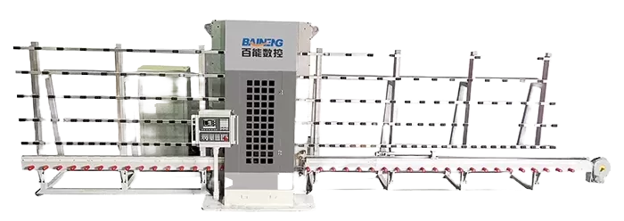
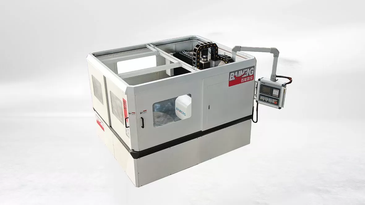
The optical glass cutting machine represents a specialized class of computer numerical control (CNC) equipment engineered to perform precise cutting, slotting, drilling, and edge-profiling operations. Unlike standard glass cutters that rely on simple scoring and breaking methods, these advanced platforms utilize high-speed rotary diamond tools combined with ultra-precise motion control systems. BAINENG CNC designs and manufactures these systems to provide industrial operators with the mechanical rigidity and operational stability required to process high-value glass substrates without compromising material integrity.
Understanding the Physical Challenges of Glass Machining
Glass is characterized by high compressive strength but very low tensile strength and fracture toughness. When a cutting tool interacts with a glass surface, the material undergoes elastic deformation before reaching its limit and fracturing. This brittle nature makes traditional machining methods highly difficult, as the energy from the tool can easily propagate uncontrolled cracks throughout the workpiece.
Micro-cracking and Sub-surface Damage
During mechanical cutting, the localized stress applied by the diamond grit on the grinding tool creates two primary types of cracks: median cracks that propagate downward into the substrate, and lateral cracks that run parallel to the surface. Median cracks directly affect the mechanical strength of the final optical component, potentially leading to structural failure under thermal or mechanical stress. Lateral cracks are responsible for surface chipping and material removal. Controlling the depth and propagation of these fractures is a primary focus of high-precision machining.
Ductile-Regime Machining Principles
Mechanical research indicates that even highly brittle materials like glass can undergo plastic deformation rather than brittle fracture under specific conditions. When the depth of cut is kept below a certain threshold—often referred to as the critical ductile-to-brittle transition depth—the material is removed through plastic flow, resulting in a smooth, crack-free finish. Achieving this state requires an optical glass cutting machine with exceptional motion control, minute feed rates, and highly stable spindle rotations. Maintaining these precise parameters consistently separates industrial-grade equipment from standard glass routing machines.
Core Engineering Features of Modern Precision CNC Systems
To consistently execute high-yield cutting programs on fragile optical substrates, the mechanical architecture of the machine must minimize vibration and deflection. Every component, from the structural base to the control software, must be engineered for high rigidity and thermal stability.
Structural Damping and Machine Base Design
High-frequency vibrations generated during the grinding process can cause tool chatter, which immediately leads to edge chipping on glass workpieces. To prevent this, quality machining centers utilize heavy-duty cast iron frames or natural granite bases. Granite offers superior vibration damping properties compared to welded steel, along with a low coefficient of thermal expansion. This ensures that environmental temperature changes in the factory do not cause structural distortion that could compromise axis alignment.
High-Speed Spindle Assemblies
The rotational speed of the spindle is directly tied to the surface speed of the diamond cutting tool. Because optical glass cutting tools are often small in diameter (ranging from 0.5 mm to 10 mm), high spindle speeds are necessary to achieve the linear speeds required for clean cutting. Spindles on these machines typically operate within a range of 24,000 to 60,000 revolutions per minute (RPM). Aerostatic or high-precision ceramic bearings are used within the spindle to minimize runout, ensuring the tool rotates true to its axis within sub-micron tolerances.
Closed-Loop Motion Control and Linear Drives
Standard stepper motors or low-resolution servo systems are insufficient for the micro-positioning required in optical fabrication. Modern systems utilize high-resolution linear encoders that continuously feedback the actual position of the X, Y, and Z axes to the controller. By utilizing closed-loop linear motor drives, the machine eliminates the backlash associated with traditional ball screws, enabling smooth, continuous vector movements along complex geometries.
Tooling and Coolant Management Systems
The interaction between the diamond abrasive tool and the glass surface generates significant heat and friction. Without adequate management of these elements, both the tool life and the workpiece quality degrade rapidly.
Diamond Tool Specifications
Tools used in an optical glass cutting machine are generally electroplated or metal-bonded diamond grinding pins, core drills, and wheel cutters. The selection of the diamond grit size is a balancing act between material removal rate and surface finish:
Coarse Grit (120 to 240 mesh): Used for initial roughing operations where rapid material removal is required, although it leaves a rougher edge that requires subsequent finishing.
Fine Grit (400 to 1000+ mesh): Used for final passes, profiling, and polishing to minimize sub-surface damage and produce near-polished edges.
Bond Type: Metal-bonded tools offer long life and wear resistance under high mechanical loads, while resin-bonded tools provide a softer cutting action suitable for delicate finish passes.
Fluid Dynamics and Particle Filtration
Coolant serves two major functions: lubricating the cutting zone to reduce frictional heat and washing away glass swarf. Glass swarf consists of highly abrasive micro-particles that, if allowed to recirculate, will rapidly erode the diamond tool and scratch the workpiece surface. Effective systems utilize high-pressure coolant nozzles directed precisely at the tool-workpiece interface. Additionally, multi-stage filtration systems, such as centrifugal separators or paper band filters, are integrated to remove glass particulates down to the micron level from the coolant reservoir.
Industrial Application Scenarios
The capabilities of a specialized optical glass cutting machine are utilized across several sectors where traditional mechanical slicing or basic laser cutting methods fall short due to thickness limitations or material sensitivity.
Consumer Electronics Cover Glass
Modern mobile phones, wearables, and tablet displays require chemically strengthened glass covers with complex perimeter profiles, camera holes, and speaker slots. Machining these features prior to the chemical tempering process requires high-throughput CNC grinding. The machinery must produce smooth, chamfered edges that eliminate micro-cracks, which would otherwise act as stress concentration points during the chemical strengthening process and reduce the drop resistance of the final device.
Optical Filters and Analytical Instrumentation
Spectrophotometers, medical diagnostic equipment, and industrial sensors rely on precise optical filters made from colored glass or coated substrates. These materials are sensitive to thermal stress, which can delaminate thin-film optical coatings or alter the transmission properties of the glass. CNC mechanical grinding using fine-grit diamond tools provides a cool, low-temperature cutting process that preserves the integrity of these delicate optical stacks.
Quartz and Sapphire Component Machining
Sapphire and quartz are highly valued for their hardness, thermal resistance, and optical clarity. However, sapphire ranks 9 on the Mohs scale, making it one of the most difficult materials to machine. Slicing and shaping sapphire wafers or quartz windows requires highly rigid CNC cutting systems paired with specialized metal-bond diamond tooling. The machine must exert steady, controlled feed forces to prevent tool deflection while grinding through these extremely hard materials.
Operational Guidelines for Reducing Scrap Rates
Achieving consistent quality in glass fabrication depends heavily on operational parameters and toolpath strategies. Operators must carefully balance feed rates, spindle speeds, and tool entry angles to achieve reliable results.
| Parameter | Roughing Phase | Finishing Phase |
|---|---|---|
| Spindle Speed (RPM) | 24,000 - 30,000 | 40,000 - 60,000 |
| Feed Rate (mm/min) | 150 - 300 | 30 - 80 |
| Depth of Cut (per pass) | 0.1 mm - 0.3 mm | 0.01 mm - 0.03 mm |
| Diamond Grit Size | D151 (Coarse) | D46 to D15 (Very Fine) |
In addition to adjusting these parameters, the tool entry and exit paths should be programmed with gradual lead-ins rather than direct plunge cuts. Directly plunging a tool into brittle glass causes a spike in mechanical stress, frequently leading to blowout fractures on the back side of the workpiece. Helical or ramping entry paths distribute the cutting forces gradually, ensuring cleaner results.
Procurement Considerations for Industrial Buyers
When selecting a CNC system for glass processing, B2B procurement teams must evaluate several technical criteria to ensure long-term ROI and process compatibility. Rather than focusing solely on initial capital cost, buyers should analyze structural specifications and operational capabilities.
Spindle Runout Tolerances: Request verified runout measurements at the maximum rated spindle speed. Runout should ideally be less than 2 microns to prevent uneven tool wear and micro-chipping.
Environmental Enclosure and Component Protection: Glass dust is highly abrasive and conductive. Ensure that all linear guide rails, ball screws, and electrical cabinets are fully sealed with positive air pressure systems to prevent dust ingress.
Software and Control Interface Compatibility: The machine controller should seamlessly import industry-standard CAD/CAM files and support specific cycles for glass-working, such as automatic tool wear compensation and touch-probe calibration.
BAINENG CNC integrates these engineering safeguards into every machine, ensuring that operators can maintain strict geometric tolerances over years of continuous multi-shift production.
Partnering with BAINENG CNC for Your Glass Fabrication Needs
Precision glass machining requires a balance between robust machine construction, high-speed rotary dynamics, and precise toolpath programming. Achieving low chipping rates and highly repeatable tolerances on materials such as quartz, sapphire, and ultra-thin glass is only possible when using equipment specifically engineered for brittle material processing.
If your manufacturing facility is seeking to improve production yields, reduce reliance on manual post-polishing, or scale up fabrication capabilities, our engineering team is prepared to assist. We offer custom configuration options, sample material testing in our application laboratory, and comprehensive training programs to ensure your system integrates seamlessly into your current production line.
To discuss your specific material requirements, obtain detailed technical specifications, or request a custom quote, please contact our sales office. Our technical consultants will analyze your drawings and production targets to recommend the most suitable system configuration for your facility.
Frequently Asked Questions
Q1: Can a standard metal-working CNC router be modified to cut optical glass?
A1: While physically possible, standard CNC routers lack the necessary spindle speeds, micro-feed resolution, and vibration damping required for glass. Additionally, metal-working machines rarely have the sealed guide rails and specialized coolant filtration systems required to handle highly abrasive glass swarf, leading to rapid mechanical wear and premature machine failure.
Q2: What is the main cause of chipping during the exit cut of a glass hole?
A2: Edge chipping on tool exit is primarily caused by a sudden decrease in back-side material support as the tool breaks through, combined with excessive axial force. To prevent this, operators should reduce the feed rate by 50% or more just before breakthrough, use a sacrificial backing plate bonded to the glass workpiece, or utilize specialized double-sided spindle machines.
Q3: Why is mechanical grinding preferred over laser cutting for thicker optical glass?
A3: Laser cutting relies on thermal shock to fracture the glass along a specified path. On thicker glass substrates (typically above 2 mm), thermal gradients can cause heat-affected zones, micro-cracks, and structural stresses that weaken the component. Mechanical grinding on an optical glass cutting machine keeps the bulk material cool, preserving its structural integrity and allowing for complex 3D profiles and chamfered edges.
Q4: How often do diamond grinding tools need to be replaced or dressed?
A4: Tool life depends on the glass composition, feed rates, and coolant quality. Over time, metal-bonded diamond tools can become "glazed" as glass micro-particles clog the matrix. Periodic dressing with an abrasive stone exposes fresh diamond grits, restoring cutting efficiency. Under typical production conditions, a high-quality tool can last for several hundred meters of cut length before requiring replacement.
Q5: Is it possible to cut chemically tempered glass on a CNC machine?
A5: No, chemically tempered glass (such as Gorilla Glass) cannot be cut or machined after the chemical strengthening process has occurred. The tempering process creates a deep layer of high compressive stress on the surface balanced by high tensile stress in the center. Any mechanical cut or scratch that penetrates this compressive layer will cause the glass to instantly shatter. All cutting, drilling, and shaping must be performed on raw glass before the tempering process.